Understanding the NF EN 12825 standard
The NF EN 12825 standard was created in January 2002.
It was created and adopted by all recognized European manufacturers. It consists of 26 pages, and is available from standards management organizations. Below are some guidelines
1. Load resistance
1.1 – Safety coefficient
The majority of European manufacturers favor the safety coefficient of 2, the coefficient 3 is only used in exceptional cases. Which means that when a system supports 450 kg for example, the manufacturer must prove that its system breaks at least at 450 x 2 = 900 kg !
1.2 – Resistance class
Resistance class maximum resistance:
- A – 2.5 mm
- B – 3.0 mm
- C – 4.0 mm
When choosing a raised floor, the specifier must choose the deflection class he wishes to obtain. It is here a notion of elasticity of the system which is sought. Do I admit that my system deforms by 2.5 mm for a load of X (class A), or can I tolerate a deflection of 3.0 mm or 4.00 mm ?
- The majority of our customers request class A, which is extremely restrictive, to the detriment of class C, the most permissive.
- When walking on a raised floor, it is natural to have a product that is resistant to effort, and not end up on a trampoline.
1.3 – Load class
(with a safety factor of 2 and 1 daN = approximately 1 kilogram)
LOAD CLASS | BREAKAGE LOAD | ALLOWABLE LOAD |
|---|---|---|
| 1 | 400 daN | 200 daN |
| 2 | 600 daN | 300 daN |
| 3 | 800 daN | 400 daN |
| 4 | 900 daN | 450 daN |
| 5 | 1000 daN | 500 daN |
| 6 | 1200 daN | 600 daN |
If you allow a load of approximately 300 kilos (3 kN) on the system, at any point, then the system will have to satisfy rupture tests of 2 x 300 = 600 kilos! .
In short, a manufacturer tells you that its system is classified 2A for example with a safety coefficient of 2, this means:
- That the system broke at various load test points at values
of at least 600 kilos - That the system withstood a load of
300 kilos at various load test points, and that the deflection never exceeded 2.5 mm!
Other examples :
- 1A – The system withstands 200 kg, the breakage is greater than 400 kg, the deflection
does not exceed 2.5 mm for 200 kg. - 6A – The system withstands 600 kg, rupture is greater than 1200 kg, deflection
does not exceed 2.5 mm for 600 kg. - 3A – The system withstands 400 kg, rupture is greater than 800 kg, deflection
does not exceed 2.5 mm for 400 kg. - 3B – The system withstands 400 kg, rupture is greater than 800 kg, deflection
does not exceed 3.0 mm for 400 kg. - 3C – The system withstands 400 kg, the breakage is greater than 800 kg, the deflection
does not exceed 4.0 mm for 400 kg.
1.4 – General principles for load testing
The manufacturer must prove that its tests are carried out according to the principles of the standard:
- The tools used to measure the results must be maintained and verified, connected to the national calibration chain,
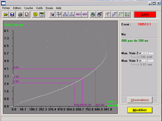
- The deformation curves must be recorded,
- The products subject to testing must be drawn at random from a production,
- The tests must be carried out, not on a single slab, but on a complete system (slab + covering + pedestal + pedestal head + stringers if necessary)
- Pre-tests must be carried out to know the weakest side of a panel (there is always one, due to the nature of the main component, wood or concrete). It is on this side that the load test will be carried out, and not on the others.
- The tests are carried out on a system which must reflect the reality of a raised floor, namely positioning of the system so that the panels are blocked, the pedestals stuck to the ground.
- The tests are carried out with a punch (25×25 mm square): in the middle of the weakest side, in the center and at the point considered to be the most at risk (generally at the corner of the panel, 7 cm on the diagonal).
- The system must make it possible to apply a regular effort at a speed of 12 daN/second
- The residual deflection measured on a system (deformation acquired by the system under pressure of the desired load class) must be less than 0.50 mm
1.5 – Supporting elements
The supporting elements of the floor panels (generally called pedestals) must resist a load equal to 4 X the admissible load. The force is axial, measured as previously at a speed of 12 daN/sec, with a 50×50 mm punch focused on the upper part of the element.2. Hard body/soft body impact tests
These tests come from foreign standards and have since been linked to this standard.2.1 – Hard body
A weight of approximately 4.5 kg, cylindrical at its end, is dropped from a height of 600 mm. It must be mentioned on the test report (PV) whether the system resisted the impact, and the deformations observed.2.2 – Soft body
A sandbag weighing approximately 40 kg, flat at its end, is dropped from a height of 1000 mm. It must be mentioned on the report whether the system resisted the shock, and the deformations observed.3. Dimensions
Having a system that resists to the load is good, but having a system that also ensures the interchangeability of elements over time is also very important !
It is for this reason that the standards include the dimensional tolerances of the systems, and in particular of the horizontal elements, the panels !
The dimensions are characterized by the dimensions taken on the sides of the panels, but also the squareness of these panels. The standard defines a precise method for these measurements. They must be measured and expressed in 1/100 mm, using calibrated instruments, linked to the national calibration chain.
The dimensional tolerances of the standard give 2 classes (1,2) according to the expected characteristics.
| SPECIFICATION | TECHNICAL SLABS CLASS 1 | STANDARD SLABS CLASS 2 |
|---|---|---|
| Length | +/- 0.20 mm | +/- 0.40 mm |
| Squareness | +/- 0.30 mm | +/- 0.50 mm |
| Straightness | +/- 0.30 mm | +/- 0.50 mm |
Respecting these dimensions is extremely important!
“False square” slabs will be unmountable, imagine a lozenge when your expectation is a square.
Also imagine a floor, well wedged, where all the panels would be 1 mm longer on one side, how to change the direction of the tile?, how to change a damaged tile with another: difficult !
Imagine again panels with a rounded side on the outside of 1 mm: unmountable! 1 mm rounded towards the inside: gaps between 2 mm slabs which will let you admire your floor from below.
A floor must be square!
There are also criteria to be met for thickness, warping (does the slab limp?), vertical warping of the slab, and height differences between the surface of the cladding and peripheral finishes.
All these specifications must be checked throughout the production process, measured during laboratory testing and recorded on the PV.
4. Other technical characteristics
The NF EN 12825 standard also describes the requirements for:
- Corrosion
- Peel resistance of PVC coverings, linoleum (soft floors)
- Reaction to fire (EN13501-1)
- Fire resistance (EN 13501-2)
- Electrostatic conductivity (EN 1081)
- Risks of electrocution
- Acoustic insulation (NF EN ISO 10848-2)
- Thermal conductivity